Sunday, 22 June 2014

‘Where you won’t find any fancy overheads.’


With apologies to the lady from Best & Less.

For years I have wanted to put up overhead wires on my layouts. When I was a kid I built some out of balsa for my British outline layout. It was a 6’x4’ board and being somewhere around twelve years old it was pretty ordinary. I did make up a jig and solder my own wires from fuse wire. I couldn’t get the bends out of it and the solder joints were far from good. I had intended to save my pocket money and buy a Lima Cl87. As I was twelve with a permanent board, the layout lasted somewhere around six months before it was changed again. The joy of set track meant that the track plan changed often. The balsa overhead masts were disposed of and never thought of again.

With the old layout on the Central Coast, I did begin to make my own stanchions again using old track and paperclips. Finding the right little beads in a craft shop was too much of a challenge and they didn’t fit onto the paperclip. I made four of these to fit under an overall station roof and hammered them into the layout. They were a little short and needed a bit of work. I also considered using the Dapol masts. Model Rail, a UK magazine ran a feature on overhead masts and I did consider ordering some from the UK as they looked about right. Then came Southern Rail to the rescue.

When planning the new layout, I had the knowledge the Southern Rail Models had produced overhead masts. As I sold a few items surplus to requirements at the Epping Model Railway Club’s exhibition on the long weekend I was able to buy some masts for my electric trains to run beneath. I drilled a few holes and presto! The open station approaches were changed forever.

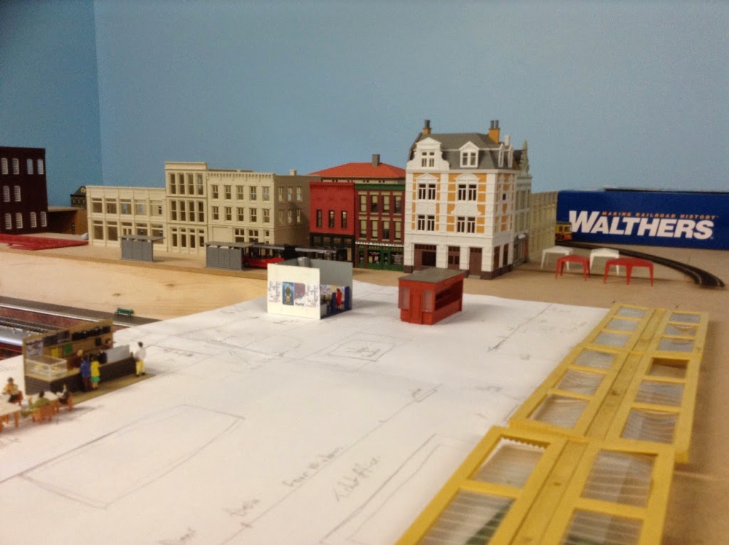
Looking from below the cathedral.

Looking from the goods yard. The line in the foreground leads to the loco depot and will the extension when it is built.
 
I know there will be some who will ‘Tut tut,’ as I write that I have no intention of installing the wires. Experience when I was twelve taught me that it is too awkward to clean the tracks with the wires in place. I had to rebuild some of the masts that I knocked over. The pantographs will be up and they will past safely under the bits that hold the wires up so the impression will be there.

I’ve spent a bit of time looking at the overhead wires and I think that I have the spacing right. At Hornsby sheds four cars fit between the posts. My station building is build above the platforms and is 60cm wide when including the road and tramway. The wires wouldn’t travel under this at the full height between the carrying wire and the contact wire therefore I would need about two car lengths between the posts and the station building structure.
I was able to buy enough posts for the station and parts of the goods yard. There are a couple of sections where the masts will need to cross four tracks but this will be a task for another day. However, I think the new masts are pretty fancy overheads.

Monday, 16 June 2014

Levels

It’s been way too long since the last blogpost. Since January, the street level went on, along with a small flurry of building work on top of it. Buildings were placed and moved, quickly painted, moved and adjusted a little bit more.

Looking across the Melbourne end of the station towards the town. The idea is that enough tall buildings will block the view of the staging yard when the operators are sitting down. The wooden wall is hiding the reverse loops. It will be lined with the same stone finish as the platforms as the station would have been built at the same time as the wall. The brick platform was added years later by the railways when it was realised that another platform was needed and bricks were cheaper than local stone.

The southern end of the station. The tracks disappear underneath the town. There will be a town hall next to the cathedral and a square with some shops. I bought the cathedral at the Forrestville Exhibition in 2012 at the bring and buy stand. I couldn't believe that someone would try to sell it. I also wondered who on earth would buy it. Turns out that it would be me. I was looking for a few small buildings to fill a block on my old layout on the Central Coast. I figured that one building would fill the gap nicely. I plan to light it from the inside and put a couple of spotlights on the outside. The carriage sidings will have a three road shed that will disguise the fact that the sidings curve to go under the cathedral.

This is the main station building. It will be built from Walthers Modular bits. It will occupy an area of an A3 sheet of paper. It will be four two storey buildings which will support a double length Peco overall roof. The Hornby platform canopies will be out the front of the main entrance and will house a tram stop. (I bought a cheap second hand one at the Castle Hill Exhibition last year.) The red and white shade shelters will have market stalls and the street will look down to a Walthers Grand Union Station which will be the city's art gallery.


Then things seemed to stop on the building front. After have a few blokes around and having them run the layout for the afternoon, I mentioned at a meeting that I wouldn’t mind setting up an operating night. There were a few who were interested.
The next step was to work out some sort of timetable or schedule for trains to run. There were a whole stack of questions that I had to which I had to find the answers.

Wednesday, 22 January 2014

The Control Panel

Control for the trains is from a Digitrax Zephyr. When I started my old layout, I needed to buy a control system. I had a couple of locos on order that had sound chips factory fitted. It was the best that I could afford at the time and with a capacity to run up to ten trains at once, it was more than I would need. It’s a great little unit but with the number of passenger cars with lights in them it does lack some grunt. Some locos were not working well. Fortunately, it is possible to switch some of the lights off and this seems to have solved the problem for a while.

The reason for using Digitrax was fairly simple. I’m a member of the Gosford City Model Railroad Club on the Central Coast and they use Digitrax. Members had built up a depth of knowledge using this brand. They had also produced their own hand held throttles, designed by someone else and capable of having locos despatched to the limited function throttles.

On my last layout, I followed some advice. This was to produce the track plan for the control panel of paper, laminate it and glue it onto a suitable board. In doing this it should be easier to change the design. On my old layout, I did this once but in doing so I replaced the 3mm ply which I was using for some plastic that I had rescued from the skip bin as it looked like thick styrene.

The circuit diagram was devised by a fellow club member and drawn on a piece of paper in a way in which I could read it. I am not brilliant with circuit diagrams beyond a simple circuit.

I had saved the old board intact and had made a few notes. Before I started, I needed more switches. I use triple pole double throw switches. Two poles power the Peco point motors and the other pole powers the LEDs that indicate the direction of the point. Each point motor has its own capacitor to avoid it burning out. The LEDs not only light up in the direction of the points but also the points that have been set beyond them to light up the route.

After starting, I found that I was short on green LEDs I had enough for the station area but not the staging yards as well. However, I had a deadline to meet. I had some people coming around from another club in Hornsby Heights to look at and run the layout. When I made the offer six weeks earlier, I was sure that I would have had the panel wired up and looking good. With a week to go I got to work, regardless of the lack of LEDs. At least the switches will show the direction of the points.
In the staging yard, I mounted the point motors above the board. It is easier. I also used the Peco side mounted motors where there was lack of space for the regular Peco motors. I must admit that they were simple to install. Where needed, I moved furniture and mounted others under the layout. There was one motor which I couldn’t use either style of motor conventionally. I mounted the motor above the baseboard and had cut a trough in the vinyl underlay and used a piece of brass rod and a plastic tube to run it underneath another set of points.

I had allowed myself a week, from start to finish, to complete this task, however, I started on a Tuesday for a Saturday afternoon deadline. I didn’t think it was a problem. A long story short... I finished at 1:30am on Saturday morning. Over fifty points all working on a 90cm board and the LEDs on the station panel were showing the route well. There is some confusion with the double slip which is shown on the panel using two switches with red toggles. That’s a task for another day.

The Panel completed and ready for visitors.
 
The LEDs for the staging yard have now turned up so they will be put in over the next couple of weeks.

The next job will be to start on the scenery and develop a sequence for operating.

During the week we had a railmotor from the Rail Motor Society drift through our local station as well as a couple of other trains.


Monday, 4 November 2013

Construction


Most people will recommend that you glue and screw timber when you work with it. I’m glad that I didn’t as it meant that I was able to reuse most of the timber frames from the old layout.

Unlike the last layout, this was designed around two feet by four feet (or 600mm x 1200mm) modules. Two modules would need to be longer (1600mm) to fit into the shed perfectly. The last layout had baseboards of various shapes and sizes.

Another change was how the layout would be supported. Advice was sought when building the old layout. I’m a member of the Gosford City Model Railroad Club on the Central Coast and one member showed me how his layout was put together. There were frames made using the ‘L-girder’ technique. Essentially, two bits of 42mm x 19mm are joined lengthways to form an L. These are combined to make your rectangular frame. Make sure that the Ls, now upside down are facing the same way where you need to attach them to the wall. On top of these you place more 42mm x 19mm timbers going across the frame, adding 42mm to the height. These timbers can be as long as you need them. To these you can add risers to lift your track bed. On the shed wall you screw bits of off cuts into the studs of the wall. These provide something for the frame to rest on as you screw it to the wall. You also need a further piece of timber or two to support it. The best way was to place the support onto the skirting board and shape the other end to fit into the L inside of your frame. I was told that it would be very solid.

It was. However, this time I was dealing with a tin shed and not an old fibro garage.

I was given advice by another member. This was to make sure that I had at least 3mm at the end of the layout for expansion. I wasn’t sure if this expansion was for the shed or the layout.

When I bought the house, the shed had shelves with some pretty serious brackets holding them up. I decided that I would use those to help hold the layout up. To these were attached sturdy timber legs that the hardware store had on special when I picked up the plywood tops. This would mean that I didn't have to worry too much about expansion of the board or the shed. The frames were made using the L-girder thinking but this time I braced them internally and placed plywood on top. The layout is going to be fairly flat where the trains run and there is going to be a lot of track. Cutting out road beds to fill in where the track isn’t going to be is not going to achieve much. Also in the planning, I realised that I would need an extra 200mm for the front modules for a bit of urban landscaping.
Under construction.
 
Once that was done it was time to lay some track.

It took a while but the track came together fairly well. I lay the track on lino. It was more advice given to me as lino off cuts are cheaper than cork. I can lay the lino out and cut around the laid track. It worked out well last time so I stuck with it. I used the thickest lino that I could, to raise the track from the board.
For some points it was their fifth layout. Some of them didn’t make it. The track was recycled and some of this was second hand on the last layout. A few new points and lengths of track were needed and an auto reverse unit for the two reverse loops was installed. It was all tested with a couple of cars from a HUB set, a Lima twelve wheeled carriage and a Bachmann 44 tonner painted as a 79 class. The high speed was far from astounding but it all seemed to work.

Once the track was down and wired up, trains suddenly appeared.
 
The next step is to motorise the points and build a control panel but that may take some time. Trains started to appear and needed to be run.

Sunday, 27 October 2013

The Plan


For years I have been admiring a plan in the back of PSL Book of Model Railway Track Plans by C. J. Freezer. The plan, Grandchester (Plan 69), has a five platform station, which is perfect for a growing collection of NSWGR passenger vehicles. The station is in the middle of the space on an oval and the layout looks like an upside down ‘e’. The footprint is similar to my last efforts. C. J. Freezer planned a branch line coming from one of the platforms. This I have had to cut and with the branch line went the modest loco depot and turn table.

In place of the turn table I have added carriage sidings and a carriage shed. The sidings need to be long enough for a HUB set. They will enter a shed and curve away underneath what will be a raised section with a cathedral on it. The cathedral was purchased at the Forestville exhibition a couple of years ago. More on this when I get the scenery started.

At the other end of the station I have added a four track marshalling yard which will curve away to the rear of the layout. I have also added an arrival/departure road for goods trains to enter the yard. I plan that most of the shunting here will be done by an operator sitting right in front of where they need to work. The uncoupling of wagons would be done on the straight sections of track after the points, so that the sidings trail of into the distance should not be a problem. Ideally, I would have preferred five tracks here, as I ended up with on my last layout but space was a bit of an issue.

Despite my best attempts, I could not fit a turn table in. I have, however, been able to squeeze in some loco storage sidings for locos awaiting their next job. They will need to be turned in the staging yard. The large cupboard is stopping any further expansion.

The staging yard caused much thought. Reading Australian Model Railway Magazine in recent years, a couple of layouts stood out with grand designs. Kangaroo Valley in the February 2012 edition had a good idea, as did Weston featured in April 2012. They have two lines for continuous running and sidings either side where trains terminate and locos swapped. The layouts can be run as a point to point scheme. The yard for Kangaroo Valley looks as though it is operated during a session as another yard. A great idea but I wanted something simpler.

I’m not sure I achieved it.

The Plan
I want trains heading to Sydney, Melbourne or any other destination to turn around and come back, like my old layout so I installed a couple of return loops. These will be hidden behind a retaining wall and under the town. Trains will leave the station, go through a return loop and then get stored, ready for their return, regardless of which direction they leave.

This has led to a different design of staging yard. I have ten tracks (the plan shows 11) and a through road. The rear two sidings will fit a 38 class and a HUB set. There are two roads that will hold longer trains with the rest holding the equivalent of a loco and 10 BCH length wagons. Off to each side, the four sidings will hold the equivalent of the U-boat set. A couple of these will be used as extra loco storage and the rest will hold multiple units of sorts.

The idea that really captured my imagination with Grandchester was the urban scenic features. C. J. Freezer drew in a road behind the station with a couple of streets running of at right angles. These streets don’t go far and are blocked by other buildings. When drawn, the layout was planned for an attic. I could use the idea in my shed.

The plan was drawn up using Anyrail software. I found it easy to use. It was a lot easier than a compass and grid paper and a lot more accurate. The grid that you plan on can be altered to different sizes and when it came to laying the track, this was a very useful feature. The design was more accurate than I could have hoped for. The lost staging road was due to cramming a bit too much in the back too close to the wall.

The plan shows that there is a large station building covering the platforms and a couple of bridges. This is so I can create an illusion that trains are longer than they are. This idea came from http://www.carendt.com/scrapbook/page94/index.html Here Allen Walker describes his layout, Prince’s Cross, and how a three coach train can appear longer if you cannot see the whole train at once. Hopefully, a similar effect can be achieved to make my eight wagon coal train look a little longer, not to mention any other train.

All I had to do was to build it.
As an aside, The Heritage Express headed to Newcastle today. The planned locomotive, 3642, wasn't up the front, most likely due to a total fire ban. Instead 4520 and 4490 did the honours of leading the train. The first shot is at Asquith this morning. The second shot is at my local station. I nearly missed it as it was running early and I was walking down the wrong side of the platform building as it rounded the bend ahead of me.


Tuesday, 22 October 2013

The Shed


The old shed 3.5m by 7m and was lined and carpeted. The new shed is 3.5m by 5.3m. Had the old layout not be bolted to the wall and built in large sections it would have fitted nicely. There was one small problem. The mower and push bikes were able to be stored under our old house and not in the shed. This is not possible at our new home. The solution of buying a new tin shed to store these in was soon realised to be impractical. There really is not sensible place to put this new shed. Any layout would need to be able to accommodate a mower and a couple of push bikes.

The mower was a simple solution. Just store it under the layout, preferably opposite the door. The push bikes however... It is amazing to think just how much space a push bike actually takes up, nearly two metres long and close to a metre wide.

Then there was the cupboard. It is 1.2m wide and is an old Department of Education 1960s vintage, storage cupboard, rescued from a fate in a skip bin. It is big, heavy and difficult to move but it is great for putting things in.

Taking all these things into consideration, furniture was moved about every now and then to see which shape would be the best. Various ideas were sketched on paper to try and find out what would work. I needed access for people to move about if I get a crew of operators, as well as a place to build models and the bar fridge. There are also two windows to consider as well.

Things to consider: bikes, desk, windows, bar fridge and a mower. And, somewhere, a layout.
 
In the end, the winner was a basic oval.  A simple design, with a staging yard at the back and the station at the front. It may seem too simple but I had to learn from old lessons that the last layout was too complicated for a single operator and it was an option that I had thought about building at our old house.

I started to build a small temporary folding layout in the meantime using some timber that I had saved from the old layout and had set aside before we moved. After a while this wasn’t going to do what I hoped it would. I came up with another idea. This folding layout involved moving furniture around the shed again. I couldn’t be bothered to do this and hinted that I could build it in the spacious back room of the house when I needed to. I mentioned this to my wife. She suggested that we should get the shed lined so that I could get on with the larger layout.
Done.
Lined, painted and ready to go. The cupboard is out of shot and didn't leave the shed during the entire process.

Saturday, 12 October 2013

Out with the old...


A house move from the Central Coast to northern Sydney saw the previous layout pulled to bits. It was the culmination of a couple of years planning, compromising and pondering. It was shaped like a backwards ‘e’. The oval held a six road staging yard with a double track mainline at the back. Part of this was to be home to part of a suburban station. As the lines came around to the middle, the two lines went through another passing station with a four road marshalling yard, a steelworks and fuel depot on the outside of the oval (next to an operating aisle) and a fairly sizable locomotive depot on the inside of the oval. The last part of the ‘e’ was a terminus based on C. J. Freezer’s Minories with an extra platform stuck in. There was also a plan to have a timesaver style layout with a pier and warehouses kicking back from the fourth platform.  Also located on the inside of the oval in front of the mainline was a little shunting area. Originally it was to be small branch line terminus with a dock for fishing boats and a small dairy siding which was later extended and included sidings for a wheat train and a ballast train. It was linked to the mainline so it became a loop line and storage for up to three trains. I was pretty proud of myself to cram this into 12 feet by 12 feet or 3.5m by 3.5m.

Trains from the terminus heading towards Sydney would take a single line the formed part of a return loop and go through the second station, past the freight yard and shed, through the third station where it would in theory disappear behind a wheat silo, reappear through the second station and then it would leave the mainline and find one of six roads in the staging yard. When the train returned to the terminus it went around the oval again, stopping at stations in the appropriate order and took an arm off the oval and headed to the terminus. Every train seemed to go clockwise with the exception of trains to the inner branch.

The idea was that I would have folks around and would hold operating sessions. It never happened. I didn’t have a shortage of folks, the layout never really reached a position where this could happen. Timetables and sequences were made up but they were complicated. Control panels were put in the wrong place; there wasn’t enough space and certainly not enough DCC control units to run the trains that I thought I would be able to run at once. After a while I realised that the only person who was going to operate the layout was me and ducking under parts of the layout to shunt trains was losing its appeal. I looked at other plans and wondered if I should start again. I could build a layout that was 18 feet by 8 feet but I didn’t think that I could handle wasting effort that I had already put in, nor that it could house all the features and industries that I had.

By this stage I had acquired a bit more stock and it was the Austrains FS/BS carriages that stopped the breaking up of the layout. The section of the reverse loop was controlled by a simple switch that I had to throw to reverse the polarities. It wasn’t a very big section and when the Austrains carriages went through it with the lights on, it caused problems.

The layout was tweaked. The timesaver section, with the pier and warehouses went, as it was hardly used, and it was replaced with three curved carriage sidings. Land was built up and a nice park with sculptures and three blocks of flats were put there. The inner loop with the fishing dock was replaced with three long sidings to hold suburban electric units and railmotors. Four long return loop sidings were build across the middle of the layout and the arm leading towards the terminus was cut and rearrange to form a couple of railmotor sidings from the station. The small single arm was duplicated and trains could now successfully run from the terminus to Sydney via the second station and then disappear into the relevant staging line. The third station was removed but now trains running to and from the terminus did so in a more sensible manner. Goods trains still went clockwise and apart from the steel works and the fuel depot, there were no other industries to shunt. However, time was still spent remarshalling trains for destinations near and far. The motley collection of buildings also had to be moved and was raised above the new return sidings. My little town now had a lot more space and instead of one road, I could put three or four streets.

The layout was now more manageable for the single operator. Although I still had dreams of a different style of layout, I decided that this was going to be finished and work on scenery was commenced. Lights on the terminus station were installed and I was excited to be working on and operating the layout.

The blocks of flats. They looked better at night.
The terminus station.
It was a small throw-away line from my sister-in-law that brought the whole thing of seven years construction to an end. “House prices in northern Sydney aren’t that unreasonable.” Less than sixteen weeks after those words were spoken we had sold a house, bought a house and moved back to the area where my wife and I grew up.
It was time to look at C.J. Freezer’s books again. I’d had my eye on one plan for a while.